

How Is Vision-Guided UV Printing Used for Hardware Tools? Saw Blades, Tape Measures and Tool Cases
A brand logo on a saw blade, a colorful design on a tape measure housing, or custom graphics on a tool case can all help create a recognizable product range. Producing these prints consistently requires more than image quality. Manufacturers also need to control artwork alignment, workpiece stability, ink adhesion and production throughput.
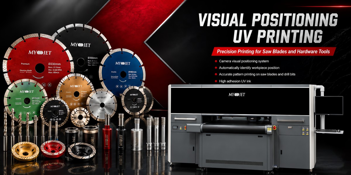
Vision-guided UV printing uses a camera to identify a workpiece’s outline or features and, after calibration and template setup, align the artwork with the detected position. It is worth evaluating for hardware products that require graphics to avoid holes, follow an edge or fit within a defined area.
The MYJET CCD120 vision-guided conveyor UV printer and the MYJET 6090 UV flatbed printer equipped with a vision positioning system can be evaluated for different production needs, from repeat batch production to sampling and customization.
What Is Vision-Guided UV Printing?
Vision-guided UV printing combines camera-based positioning with UV inkjet printing. The camera supplies workpiece location information, and the printing system uses a configured recognition template and artwork relationship to position the print.
A typical workflow includes:
1. Template setup: Define the recognition features, artwork orientation and printable area.
2. Workpiece loading: Place the product on the flatbed or conveyor, using supporting fixtures when needed.
3. Position detection: Identify the outline, holes or other stable features.
4. Printing: Output the prepared artwork according to the detected position.
5. Inspection: Check alignment, appearance and adhesion.
Vision positioning primarily addresses alignment within the printing plane. It does not replace workpiece support or automatically compensate for curved surfaces and height differences.
Which Hardware Products Are Suitable for Evaluation?
Suitability depends on more than the product category. The key questions are whether the item has a stable printable surface, recognizable features, secure placement and a surface compatible with the selected ink.
Information used for functional or safety identification also requires verification of legibility and durability for the intended application.
Saw Blade Printing: How Can Artwork Stay Aligned with Holes?
One challenge in saw blade printing is maintaining the correct relationship between the artwork, center hole, auxiliary holes and outer edge. This matters when a design includes circular text, graphics that must avoid holes, or markings with a defined orientation.
Two positioning questions should be considered separately:
· How will the center be located? Stable features such as the outer circle or center hole can be evaluated.
· How will the rotational orientation be determined? Auxiliary holes, slots or other directional features may be needed.
A perfectly symmetrical outer circle and center hole cannot, by themselves, distinguish rotational orientation. Direction-sensitive artwork requires an additional recognizable feature or a fixture that controls the blade’s orientation.
MYJET CCD120 Saw Blade Printing Throughput Reference
According to test data supplied by MYJET, the CCD120 achieved approximately 2,000 saw blades per hour under the following configuration and application conditions:
This figure applies to the stated test conditions. It should not be directly applied to other blade sizes, artwork coverage levels or ink-layer combinations. Each project also requires confirmation of print mode, loading spacing, recognition conditions and any additional white ink or varnish layers.
Equipment evaluation should consider printing speed, loading and unloading capacity, and acceptable finished output together.
Tape Measure Housing Printing: Define the Flat Area First
Tape measure housings are potential applications for brand logos, colorful decoration and promotional customization. However, housing designs vary considerably. Some have relatively flat sides, while others include curved surfaces, rubber sections, recesses or metal clips.
Before preparing the artwork, check:
· Whether the intended print area is sufficiently flat.
· Whether the housing rocks or tilts when placed.
· Whether raised structures interfere with printhead clearance.
· Whether the material and surface finish suit the selected ink.
For housings with curvature or edge height changes, start by concentrating the artwork within the flat area. Sample testing can then establish the usable print boundary.
Vision positioning helps align the artwork, but unstable housings still need suitable support or fixtures.
Tool Case Printing: Start with the Central Panel
Tool cases and hex key set cases can carry brand logos, product series names and tool-themed graphics. Exhibition samples can also use color and spot varnish to demonstrate decorative effects.
The lid is not necessarily flat across its entire surface. Edges, reinforcing ribs, hinges and latches can limit the printable area.
A practical design process is to:
1. Measure the usable flat area in the center of the lid.
2. Leave clearance around height changes, holes and structural features.
3. Place the logo and key text near the visual center.
4. Test positioning and adhesion with a small design before finalizing the layout.
When combining white ink, color and varnish, check white coverage, color appearance and varnish alignment separately. Varnish effects should also be confirmed using the actual machine configuration and print mode.
What Should Be Tested Before Printing on Metal or Plastic?
Accurate positioning does not guarantee strong ink adhesion.
Products described as “metal saw blades” or “plastic tool cases” may have different coatings, surface treatments or residues. UV ink can be used on various metals and plastics, but some materials require primer or another compatible surface treatment. Actual samples should be tested before production. [1]
If primer is required, use a product compatible with the substrate and ink system, following the supplier’s application instructions.
MYJET CCD120 or 6090: Which Should You Evaluate?
Start with the order mix and production workflow, then compare machine configurations.
For ongoing batch production of similar workpieces, start by evaluating the CCD120. For frequent changes in products, artwork or fixtures, start by evaluating the 6090 with vision positioning.
The final choice should be based on testing with the actual products. Vision positioning and white, color and varnish capabilities must be confirmed for the selected machine configuration.
Frequently Asked Questions
Can vision-guided UV printing eliminate fixtures completely?
Not always. The vision system identifies position, while fixtures support and secure the workpiece. Products that roll, tilt or move during transport may still need fixtures.
Can a saw blade’s center hole determine artwork orientation?
A circular center hole alone cannot determine rotational orientation. Rotationally symmetrical workpieces require an additional directional feature or controlled fixturing for orientation-sensitive designs.
Does the MYJET 6090 support vision-guided printing?
Yes. The MYJET 6090 can be equipped with a vision positioning system. A project evaluation should confirm the vision configuration, workpiece dimensions, height and recognition conditions.
Does every hardware product need white ink?
No. White ink requirements depend on the substrate color, artwork and intended appearance. Color graphics on dark substrates can be evaluated with a white underbase, while designs intended to retain the substrate’s original appearance need a suitable layer structure confirmed by sampling.
Are UV-printed graphics automatically scratch-resistant?
No. Performance depends on the material, surface preparation, ink compatibility and conditions of use. Testing should reflect the intended product application.
Can every CCD120 saw blade job reach 2,000 pieces per hour?
No. Approximately 2,000 pieces per hour is a MYJET-supplied test reference for 115 mm saw blades using four Ricoh G6 printheads in a single-row color configuration. Other production conditions require separate evaluation.
Evaluate a Printing Solution for Your Hardware Products
Before choosing a UV printer, prepare product photographs, dimensions, material and surface finish details, together with artwork showing the intended print position.
Target throughput, order quantities and white ink or varnish requirements will help define the machine configuration and production workflow.
Contact MYJET with your saw blade, tape measure housing or tool case application to evaluate a CCD120 or 6090 vision-guided UV printing solution.
GET IN TOUCH